For a brief early history of the Frigate USS Constitution click here.
For information about building the model hull of Constitution, including information
on source of plans and building techniques click here.
For information about creating the shipyard diorama and modeling the processes
and supplies involved in building a ship of that time click here.
After the American Revolutionary War, with the nation heavily in debt, the new United States
Congress disbanded the Continental Navy to reduce expenses,
and in August 1785, sold its last remaining warship, the "Alliance". Toward the end of that century,
however the "Barbary States", the city-states of Algiers, Tripoli, and Tunis, along the north
African shore of the Mediterranean began raiding merchant shipping in the Mediterranean and the
adjacent Atlantic. American shipping had been protected by the British Navy prior to the
revolution, but the sea-raiders took advantage of the American's new unprotected status
to capture American ships, seize the cargos, and enslave or hold for ransom the crews.
Largely in response to the "Barbary Pirates" problem, but also with a view to
possible future naval engagements, the United States Congress authorized the building
of the original "six frigates" of the United States Navy with the Naval Act of 1794,
thereby establishing a United States Navy. These ships were built on the recommendation of
ship designer Joshua Humphreys
that the new nation build a fleet of frigates large and powerful enough to engage any frigates
of the French or British navies yet fast enough to evade a ship of the line.
Since, to some
extent, the speed of a ship was related to the amount of sail she could carry, large ships
with tall masts and larger, sturdy spars carried more sail so often had the advantage of speed.
Sail area was not the
only determinant of speed, as the displacement, weight, and shape of the hull mattered, as well as
the type of rig, and, of course, the skill of the sailing master and the crew. So, in one
respect, Humphreys was correct: a larger frigate with taller masts and longer spars would
have a speed advantage over a smaller frigate, unless the hull design or condition of
the larger vessel slowed her down. And at some point, the larger frigate, with a more
narrow hull, a sharp bow and a single gun
deck, carrying less armament (weight) and an expanded sail area might be able to match or
exceed the speed of a heavier ship of the line, particularly as there were limits to how
big a wooden
hull could be built, limits to how tall a mast or spar could be, and limits to
how large a sail could be and still be handled by the crew. Somewhere there might be a
sweet spot where the frigate could be big enough to carry sufficient sail area relative to
the hull displacement that it could out race a ship of the line. But for practical
purposes, most of the time a larger ship traveled with other ships when patrolling for
enemy, often smaller, faster ships there to seek and find prey and accustomed to
operating together when engaging an enemy ship.
To be fair, at
that time, the concept of the "heavy frigate" was new and evolving, so the planners on the
American side could be pretty certain that any enemy "frigate", despite sharing a class name,
would be much smaller, more lightly built, and armed with smaller guns, generally 12 to 18
pounder long guns. At that time also
in warship design evolution, designers on both sides of the Atlantic were developing hulls of
narrower, sharper shape, without the bluff rounded bow formerly favored. The French were
leaders in this trend, with the Americans not far behind. The British were slower to adopt
the new designs, but before long, during the Napoleonic wars, they began to copy the design
of fast ships captured from the French, as well as taking into the Royal navy the faster ships
of American and French design.
In the end, the American heavy frigates were certainly more
than a match for lighter frigates they encountered, but were hardly able to out run
larger rated ships, especially when the latter operated in convoy, and were pretty
evenly matched by the British heavy frigates that began to appear by the
War of 1812. The ultimate fate of these
original six heavy frigates attests to these latter realities. See here.
\
Prior to the Navy Act of 1794, lacking a navy, the United States could do little to protect
their merchant ships from piracy. Many in Congress felt it less expensive to ransom captured
crewmen and to pay "tribute" to the pirate states rather than build a navy to suppress the piracy.
Naturally, there was a great deal of opposite sentiment in Congress and in the United States
government. During the debate over the question of how to deal with the North African
pirates and whether to re-establish a navy, things got more complicated when, after the French
Revolution, the British navy began seizing American ships suspected of trading with the French,
while the French navy began seizing American ships suspected of trading with the British. This
situation, or perhaps this insult to American sovereignty finally tipped the balance in the debate.
And was hardly fixable by paying "tribute".
On January 2, 1794, by a narrow margin of 46–44, the House of Representatives voted to authorize
building a navy and created a committee to determine the size, cost, and type of ships to be built.
To appease the opposition, the Federalist Party inserted a provision into the bill that would stop
construction of the ships should the United States reach a peace agreement with Algiers. This was
a last minute compromise to get the additional votes needed to pass the full act act, to authorize
a Navy, but the provision was short-sighted, as it
ignored the increasing difficulties with both Britain and France.
The final bill, which included funds for naval officers, sailors, and marines,
was passed by the House as the "Naval Act of 1794" by a margin of 50–39, and
by the Senate on the 19th of March, 1794. President Washington signed the Act
on March 27. The Act provided for acquisition, by purchase or otherwise, of four ships to carry
forty-four guns each, and two ships to carry thirty-six guns each. It also provided pay and
sustenance for naval officers, sailors and marines, without whom the ships would have been
useless.
Since there was no Navy Department, responsibility for the design and construction
of the ships fell to the Department of War, headed by Secretary Henry Knox,
who consulted with a number of ship designers and builders in Philadelphia about planning
for these first ships of the new Navy.
Details of whom Knox met with and what was discussed are not known, but Joshua
Humphreys is widely regarded as the primary designer of these six frigates. Revolutionary
War ship captains John Foster Williams and John Barry and shipbuilders Josiah Fox and
James Hackett also were involved in the design process. Humphreys
had for some time advocated building "heavy frigates", and his ideas are certainly
reflected in the design of these vessels, most notably the Constitution. Also, during the
planning, the decision was made to build rather than buy the ships and to build
all six: four of 44 guns and two of 36 guns.
The final hull design was unusual for the time, with a deep and long hull, a narrow beam, and a
sharp bow where the hull entered the water. Not a "clipper" type sharp bow, but much
different from the full bluff bows characterisic of most ships of the time. The
long length of the ships was possible because of the availability of large quantities of
suitable timber in the United States, unlike England and the continent, where centuries of
ship building had depleted forests and supplies of virgin timber. Also, the design included
diagonal braces along the inside of the ribs/frames of the hull to counteract the "hogging"
that would otherwise occur with a long hull carrying heavy
armament. Hogging refers to the tendency of a hull to sag at the front and the rear after
a time, or even at launch, due to the fact that the bow and stern of a ship are narrower than
the middle, so therefore have less buoyancy because they displace less water. But on warships,
the weight of the guns is distributed pretty much along the entire length of the hull, making
the weight relatively greater at stem and stern due to the reduced buoyancy. This relative
weight disparity often resulted in the ship's keel bowing downward at the ends, sometimes
to significant degree. This affected the performance of the hull and, more importantly, stressed
the hull in different ways than planned for. The use of diagonal "riders" was not especially
new or unusual, as English builders also used the technique, but when combined with the massive
sizes of the frame timbers, it produces a remarkably strong hull and resists hogging.
Once the plans were final, and the costs recalculated, Knox advised President Washington that
the cost of new construction of the frigates
would likely exceed the appropriations of the Naval Act. Despite this, Washington accepted and
approved the plans the same day they were submitted, April 15, 1794.
Joshua Humphreys was appointed Master Constructor of the ships. An experienced draftsman,
Josiah Fox, was hired into the War Department to put plans to paper. However, Fox disagreed
with the large dimensions of the design and, according to Humphreys, attempted to downsize
the measurements while producing his drafts. Evidently, when Humphreys found out about this
change in the design, he demoted Fox to serve in the drafting loft. A William Doughty was
working in the drafting loft and it is Doughty who is credited with the surviving draught
of the Constution hull in the National Archives. This "Doughty Draft" is generally thought
to most likely represent the
design of the Consitution and her sister ships at the time of launch.
Along with drawing up the plan for a ship, a builder's half model was worked up from the plan.
In the "molding loft, this half hull model was scaled up into full size templates laid out on
the molding loft floor and then made up of thin wood. These wooden templates were used by the
timber crews to select trees or parts of trees to be used in making the frames, which had curved
portions. Once the trees had been selected and cut and transported to the ship yard.Later, in
the ship yard, the molding templates were used by the ship carpenters to make up the individual
frames.
The actual frames consisted of two halves, thick timbers fastened together side to side
with the joints of each half staggered so not to coincide and make a weak spot.
The component parts of a frame were
called "futtocks", and a frame for a ship like these frigates could have as many as six futtocks
as the rose from the keel to the top rail. On the plan of the ship, the position and number of
the frames are specified as well as the position of the "first futtock" for each half of each frame.
The location of the division between subsequent futtocks was usually left to the carpenters to
decide based on current practice. The frames were massive, much heavier on a warship than a
merchant ship,
since the warship not only had to carry heavy armament in addition to cargo and crew, but also
had to withstand the pounding of the round shot fired by cannon of the time. The Constition, for
example, had frames that measured twenty-two inches from front to back and ranged from twenty-four
inches thick gradually reducing to four inches thickness at the top end of the frame.
The frames were spaced two inches apart,
and were covered with external planking four to six inches thick and interior planking four inches
thick. A wall of solid oak two feet thick or more.
In an early example of federal government "pork", the War Department decided that the six
ships would be built at six shipyards scattered among the states, rather than building at one
particular shipyard. Separate locations enabled the allotted funds to stimulate each local economy,
and probably assuaged any hard feeling among those who had opposed the recreation of a Navy.
At each site, there was a civilian naval constructor to direct the work and Navy captains appointed
as superintendents, one for each of the six frigates as follows:
Ship
Site
Guns
Naval Constructor
Superintendent
Chesapeake
Gosport, VA
44
Josiah Fox
Richard Dale
Constitution
Boston, MA
44
George Claghorn
Samuel Nicholson
President
New York, NY
44
Christian Bergh
Silas Talbot
United States
Philadelphia, PA
44
Joshua Humphreys
John Barry
Congress
Portsmouth, NH
36
James Hackett
James Sever
Constellation
Baltimore, MD
36
David Stodder
Thomas Truxtun
The frigates were originally designated by the letters A through F until March 1795, when
President
Washington named five of the ships: "Constitution", "United States", "President", and "Congress",
each representing an element of the U.S. Constitution along with "Constellation", named for
the thirteen stars on the Arms of the United States. The sixth frigate, "Chesapeake", was named
for the Chesapeake Bay in 1799 by the Secretary of the Navy and is the only frigate not
named for some basic element of the United States government.
Construction of these "six frigates" was to use the strongest and most durable materials available
in the United States.
This meant white pine, longleaf pine, white oak, and southern live oak among others.
Live oak was used for framing because it is strong, dense, and long-lasting. The wood weighs up to
75 lb per cubic foot (1,200 kg/m3) when green, 62 lb per CF when air dried. For contrast,
white pine weighs about 36 lbs/cf green and 25 dry, white oak 62 green and 48 dry. Although
there are harder woods, such as ironwoods ( as much as 86 green, 80 dry) and lignum vitae
(89 green, 79 dry) these woods are hard to work, dull tools, and are not native to the U.S
(lignum vitae) or not found in the states that made up the original thirteen (ironwoods).
The live oak tree grows primarily in coastal areas of the southern
United States from Virginia to Texas, with the most suitable timber found in the coastal areas of Georgia
near St. Simons, which is where the live oak for the frigates was to be harvested.
This desire for live oak was the primary cause of delays in the frigates' construction.
Appropriated funds from the Naval Act were not available until June 1794. The earliest delivery of
timber occurred in Philadelphia in December, and problems with timber supply continued through
1795,but by December of that year all six keels were laid down, but the hulls unframed.
Construction continued until the 1796 announcement of the Treaty of Tripoli,
which was signed by Algiers. The clause in the Naval Act, stipulated that construction of the
frigates was to be discontinued. However, President Washington instead requested instructions from
Congress on how to proceed, and a compromise was worked out reulting in the decision to
complete the three
ships furtherest along: United States (44) Constitution (44) and Constellation (36). But construction
of the other three ships was stopped.
Congress grudgingly appropriated more money in 1797 to complete the three frigates, but no money
to finish equipping them for sea and no money for crew.
United States launched on May 10, Constellation on September 7, and Constitution on October
21, 1797.
When the next session of Congress convened in November, Secretary McHenry requested funds to
complete the three frigates. Though upset over the escalating costs, Congress approved additional
money, but simultaneously launched an investigation into possible waste or fraud in the frigate
program. In March, 1798, McHenry turned over a report outlining several main reasons for cost
escalations and these findings led to the formation of the Department of the Navy on April 30, 1798.
Meanwhile, relations with France were deteriorating further and war with this former ally seemed
likely. Congress was finally spurred to appropriate money to fit out the three completed frigates
for sea duty and to finish building the three remaining ships: Congress (36) launched in August, 1799,
Chesapeake (44) in December the same year, and President (44) in April, 1800. The United States
finally had a navy.
Armament of the American Frigates
The 44-gun ships usually carried over 50 guns, and Constitution mounted 24-pounder guns
in her main battery instead of the normal 12 and 18-pounders most frigates of the time carried.
The Naval Act of 1794 had specified 36-gun frigates in addition to the 44s, but at some point the 36s
were re-rated as 38s. Their "ratings" by number of guns did not correspond to actual number of
guns carried, and sometimes not even to the number of guns in the main battery. Frigates had a
single gun deck with a partial deck covering the bow area (forecastle) and a partial deck covering
the after part of the ship (quarter deck), usually from just behind the main mast to the transom.
These two decks were generally connected with walkways between them and were together
referred to as the "spar deck". Guns mounted on the spar deck were often not counted in the
total number of guns a ship was rated for, although in some cases, some were.
Constitution,
for example, was originally built with fifteen gun ports on each side, which would imply a main
battery of 30 long guns. She did have openings in the railing of the quarter deck and forecastle
which would represent an additional seven (quarter deck) plus three (forecastle) guns, bringing
her total maximum possible gun count to fifty. But the guns on the quarter deck and forecastle
were lighter than the main battery, and probably she did not mount guns in every opening in the
rails on those decks. Soon after launch, she was modified by the addition of a sixteenth gun
port toward the bow, but this port may not have always carried a gun, unless battle planning
required it.
Ships of this era actually had no permanent battery of guns.
The cannons were portable, and often were moved about on the vessel depending on the mission or
transferred to other ships or shore batteries as needed. Each commanding officer set up the
battery of his ship according to his preference for weaponry, the availability of guns of a
particular type, the mission being prepared for, the overall weight of any additional cargo, the
route to be sailed, and the availability of personnel on board the ship.. And any given ship
evolved with time,
experience, and various commanders. Constitution, as mentioned, acquired an additional gun port
forward of the original first port so that guns of the main battery could be aimed more forward
when giving chase or engaged in attack at an angle. Records of changes in the
arrangement or even the size or type of gun were generally not kept, just as
changes or modifications of the rigging and sails were not. And many ships carried smaller
long guns as bow-chasers or stern-chasers. These were sometimes of brass, believed by some
commanders to be more accurate, and may or may not have been counted in the listing of the ship's
armament. Sometimes these guns belonged to the captain personally and came and went with him.
To further complicate the matter, there were also carronades. The carronade, named for the
Scottish Carron Company Ironworks, which developed and manufactured the first versions. Both
long guns and carronades were smoothbore and generally of cast iron. Gun casting and boring
techniques were pretty primitive in the 18th and early 19th centuries and guns were prone
to problems of accuracy and durability, the bursting of a gun when fired not being uncommon.
Further, the solid iron round shot fired by these guns would rust in storage. One task aboard
ship was the chipping of the rust off the shot. Since the diameter of the shot and the diameter
of the gun bore was at best only approximately the same, the shot was put into the gun
wrapped in cloth to make the fit
tighter and reduce "windage", the loss of propulsive force due to gasses leaking around the
projectile rather than pushing it forward.
Around 1770, the Carron Company produced a novel version of the long gun initially for the purpose
of defending merchant ships from attack and boarding. Since merchantment were not
expected to have crews accomplished in gunnery, not that even the best naval gunnery was
very accurate, the Company developed a shorter, lighter version of a cannon designed for
close combat. The Company also developed better manufacturing techniques for the gun and
supplied the projectiles (round shot, grape, canister, etc.) so that the better fit of
the projectiles in the gun reduced windage and increased the power of the firing. These
guns were also mounted differently, being fastened by a loop or similar fitting on the
underside to a wooden or metal platform which was in turn fastened by a pin to the
bulwhark/waterway of the ship at the gun port. This carriage had slides to allow the
gun to move backward with recoil and also to pivot side to side to aim. Early on,
the carronades were built with an elevating screw at the back, further simplifying
the aiming of the gun. All these differences permitted the carronade to be shorter, have
larger bore, require a much smaller gun crew to operate, and be light enough to be
mounted on upper decks. And they were devastating at short range.
The carronades proved successful for their intended purpose and were widely adopted
by merchant vessels, especially British, by the late 1770s.
In time, the Royal Navy took note, and began to equip some ships with carronades
on a trial basis. Initially, carronades weren't even counted when enumerating a
ship's armament. But the early experiments were very successful, and several
encounters with French ships proved the usefulness and destructive power of the new
weapons in the early 1780s. Admiral Lord Nelson was an enthusiastic proponent of
the use of carronades, calling them "my smashers", as they fit well in his battle
tactic of closing as quickly as possible with the enemy, lashing the hulls together
if possible, boarding and fighting hand to hand. HMS Victory was Nelson's flagship at
Trafalgar. She was a first-rate ship of 104 guns. Her armament included (Gundeck) thirty
long 32-pounders, (Middle gundeck) twenty-eight long 24-pounders,(Upper gundeck) thirty
short 12-pounders, (Quarterdeck: twelve short 12-pounders, and (Forecastle) two
medium 12-pounders, and two 68-pounder carronades. It is these last two guns, the
carronades, that fired through the stern windows of the Beucentare, the flagship of the
French fleet, clearing her decks along with a full double shotted broadside.
The carronade, however, because of the shorter length of its barrel, was regarded
as inaccurate at longer range and unsuitable for any use other than close action.
Probably, the accuracy was not much different that the long guns of the day. Or,
better stated, the two types of guns were probably equivalently in-accurate. Naval
combat tactics changed after Nelson's time, and ships began to avoid
close engagement and rather stand off at a distance using longer range cannon in an
attempt to disable the enemy through damage to the rigging or injury to the crew.
It was improvements in cannon and shot manufacture that produced some improved
accuracy allowing the stand-off bombardment, and the later introduction of rifled barrels
and shell projectiles further greatly improved the accuracy of naval gunnery.
These changes virtually elimated the need for close in action, and for the carronade, as naval
battles evolved into more long range affairs with improved accuracy and range. By
the mid 1800s, carronades were pretty much extinct.
For long guns of the size carried on the American frigates, twelve men and a powder-boy were
needed to operate each gun. The guns were aimed by using tackles on each side to move it to the
left or right, and a quoin (wedge) at the back of the gun to elevate or depress the muzzle. Once the
cannon was loaded, it was pulled out the open gun port with additional tackle, and when ready to fire,
the head gunner
lit the powder in the pan with a slow-match or used a flintlock trigger to detonate the black powder
in the gun. All this was done aboard a ship that was pitching up and down working on decks which
were not only moving, but also slick with water and sometimes blood. It is really amazing that the
gun crews of the time were able to hit anything, and certainly explain Nelson's preference for
close in engagement, where guns were fired at point blank range.
The batteries could be fired all at once as a "broadside" or individual crews
could fire as they were ready and could aim and fire. Once the cannon was fired, the recoil and
a rear mounted tackle combined to haul the gun back inside the bulwark so a man could use a wet
cotton swab to extinguish any remaining burning remnants of powder from the shot and wadding
left in the bore of the barrel. Then the crew loaded the barrel with alternating layers of black powder
and wadding and compressed the powder before adding the cannon ball or other projectile, usually
also wrapped with cloth to make a good seal with the barrel. And then the gun was primed with more
powder added to the passage from the inside of the barrel to the shallow powder pan on the outside
of the top of the cannon and the gun was ready to fire again. A good gun crew could fire and reload
and be ready to fire again in less than a minute.
As mentioned above, carronades required smaller gun crews, and could be operated by merchant
seamen with less experience in gunnery, especially when used in close action, as when repelling
boarders.
Shipboard cannon fired several different types of projectiles. First was round shot, a solid cast iron
sphere, and a cannon was
rated or designated by the weight (in pounds) of the round shot it fired. Other types of shot could be fired
if circumstances dictated. There was grape-shot, a bundle of smaller round projectiles held together
with a clamp or bag which was used mainly against personnel. There was chain shot, two balls connected
by a short length of chain, which was used to damage or disable the rigging of an opponent, and bar
shot, looking like its description, which was also used against rigging and personnel. In addition,
gun crews sometimes added scrap metal and nails and the like to grape shot as additional anti-personnel
projectiles. And sometimes, the crews fired heated round shot used to start fires on an opponent's
ship or a shore target. The heated shot was sometimes a problem, as it had to be heated in a
small oven on the ship and was therefore a fire hazard on the ship, and once heated, it had to be
handled with
metal tongs when carried to the gun, and sometimes, once heated, it no longer fit in the gun barrel
due to expansion, and was likely to detonate the black powder in the barrel. So heated shot was more
technique used by shore batteries
.
In addition to the gun crews, there were also marines stationed in the fighting tops as sharpshooters
directing fire onto the deck of an opposing vessel as well as marines stationed on deck along with
additional armed crew to repel boarders or to form a boarding party to attack the opponent.
Survived the war; captured by Confederates in Civil War
Launched May 10, 1797 in Philadelphia. Her original captain was John Barry,
a hero of the revolution. During the War of 1812, she was captained by Stephen Decatur Jr.
and captured HMS Macedonian.
By 1861, USS United States was rotting in Norfolk when captured by Confederate forces.
She was then commissioned CSS United States, often called CSS ‘Confederate’ States,
(a fitting metaphor for the divided nation). A year later, the Confederates abandoned
the navy yard and sunk CSS United States to block incoming Union ships. It’s said that
an entire box of axes was ruined as they attempted to scuttle the ship, making it
necessary instead to bore through the hull.
After Union troops recaptured the Norfolk Navy Yard, USS United States was raised,
but soon after broken up for scrap wood.
USS Constellation:
Survived the war; rebuilt/replaced in 1853
USS Constellation, the second of the first six frigates completed, launched Sept. 7, 1797
in Baltimore. Commanded by Capt. Thomas Truxton during the "Quasi-War"
with France (1798-1800)she outfought two French ships, capturing one, L’Insurgente (40) a 12-pounder
frigate, and damaging the other, La Vengeance (48) an 18 pounder frigate. She captured
L’Insurgente in a lopsided battle, suffering only two casualties to her opponent’s 29.
In about 1853, the name Constllation was transfetted to a 22 gun sloop of war, which is
the vessel currently displayed in Baltimore's Inner Harbor. It is not clear what
happened during this "re-building" but some information suggests that there was some
bureaucratic sleight of hand involved, in which the older Constellation was
laid up for repairs and rebuiding and emerged a different ship. This was not an
unusual practice when money for new ships was not available, but money for repair was.
Whatever really happened, it is nice to believe that the present USS Constellation has
some of the wood from the original in her. For those who need convincing that the ship
presently on display is not the originall vessel, is it only necessary to look at the round
stern, lacking the old style transom, to know the truth. By the 1830s round sterns were
the preferred way to build, and even by the 1820s builders were making the transition.
See builder's .notes
on the model of Vandalia.
USS Chesapeake:
captured by British
Launched on Dec. 2, 1799 in Gosport, now Norfolk, Va. she was one of the
44 gun frigates. She made her first capture of a French privateer after a 50 hour chase
during the Quasi War,(1798-1800), However, she became known
for two other disastrous events associated with her name.
The Leopard Affair
In the spring of 1807, during the
Napoleonic Wars, ships of the British Navy were blockading two French third rates in
the Cheaspeake Bay. Deserters from the British ships were welcomed in the Virginia cities
and were abroad on the streets of Norfolk. Some even enlisted in the U.S. Navy. The British
consul requested the commander of the Gosport (Norfolk) Navy Yard,
Stephen Decatur turn over the deserters to no avail. Some of the deserters were rumored
to have joined the crew of the Chesapeake, then outfitting in the Washington Navy Yard.
The Vice-Admiral of the north
Atlantic squadron sent HMS Leopard, a fourth rate Frigate with orders to board American
warships and search for deserters among the crew.
Subsequently, after leaving port and heading for duty in the Mediterranean.
Chesapeake was off the coast of Norfolk,
Virginia, commanded by Commodore James Barron, when Leopard, under a Captain Humphreys,
encountered and hailed her. Barron was not alarmed, and received Lieutenant John Meade on board,
who presented Barron with a search warrant. After an inconclusive discussion, Meade returned to
Leopard and Captain Humphreys ordered the American ship to submit. When
Chesapeake did not, Humphreys fired a round across her bow followed immediately by
repeated broadsides into the American ship. Chesapeake, with her guns unloaded and her decks
cluttered with provisions for the long trip ahead, managed to fire only a single gun before
surrendering and striking colors. Chesapeake lost three killed and 18 wounded.
Humphreys refused the surrender and sent a boarding party to search for deserters.
There were scores of British national in the crew of Chesapeake, but
Humphreys took only the four Royal Navy deserters on the ship. Although all had been in the
Royal Navy, only one, a Jenkin Ratford, was a British national, the others were American
citizens, two of them African American. Leopared sailed to Halifax where Ratford was tried,
convicted, and hanged. The three American deserters eventually had their sentences of
500 lashed commuted.
The bloody encounter and the outrageous behavior of the British captain was
protested by the U.S Government and the British government eventually returned
the three Americans and offered to pay reparations for damage to the Chesapeake.
Battle with HMS Shannon
During the War of 1812 while undergoing repairs in Boston, her Captain, James Lawrence,
accepted a challenge from Captain Broke of HMS Shannon (38) for a ship-to-ship duel.
The ships were evenly matched, with nearly identical size, displacement, and armament, but
Broke had been captain of Shannon for several years and had modernized his battery and
trained his crew. Lawrende was newly in command of Chesapeake with a motly crew of
old hands combined with new recruits and transfers from Constitution.
Cheaspeake sailed out of the harbor to engage Shannon. The Chesapeake was quickly
overtaken by Shannon and, in a battle lasting about 15 minutes, Chesapeake was badly
out gunned-and quickly boarded by the Shannon's crew. Though mortally wounded,
Lawrence continued calling
to his Sailors the famous words: “Don’t give up the ship!”. Chesapeake had 48 men killed,
including
the captain and all lieutenants, and 99 wounded. Shannon had 23 killed and 56 wounded.
Shannon was a Leda class Frigate of 1065 tons, being 150 feet long, 40 feet wide and 12'11"
deep. She carried 28 18-pounder long guns on the gun deck, and 16 32-pounder carronades and
ten 9-pounders on the quarterdeck and forecastle. Crew was 330.
Chesapeake was 1244 tons, with length of 152 feet, beam of 41'3" and draft of 20 ft. She
carried 29 18-pounder long guns on the gun deck and 18 32-pounder carronades plus
two 12 pounder long guns and one 12 pounder carronade. Crew was 340.
Chesapeake went on to serve in the Royal Navy as HMS Chesapeake for the remainder of the war.
She was later scrapped and the wood used to build the Chesapeake Mill,
still located in Wickham, England.
USS Congress:
Survived the war scrapped in 1834
Congress launched Aug. 15, 1799 in Portsmouth, N. H. She was the second of the "small"
frigates, rated at 38 guns and carrying 28 eighteen pounder long guns and 12 9-pounders at
launch, later changed to 24 18-pounder long guns and 20 32-pounder carronades. She served in
all of America’s early naval
conflicts including the Quasi War, the first Barbary war, and the War of 1812.
Her first duties with the newly formed United States Navy were to provide protection
for American merchant shipping during the Quasi War with France and to defeat the Barbary
pirates in the First Barbary War. During the War of 1812 she made several extended length
cruises in company with her sister ship President and captured, or assisted in the capture
of twenty British merchant ships. At the end of 1813, due to a lack of materials to repair her,
she was placed in ordinary for the remainder of the war. In 1815 she returned to service
for the Second Barbary War and made patrols through 1816.
In the 1820s she helped suppress
piracy in the West Indies, made several voyages to South America, and was the first U.S.
warship to visit China. Congress spent her last ten years of service as a receiving ship
until ordered broken up in 1834.
USS President:
Captured by British
Last to launch was USS President on April 10, 1800 in New York, N.Y. At the beginning of the War
of 1812 President sailed with USS Congress and was able to capture several merchant vessels.
The United States declared war against Britain on 18 June 1812. Three days later, within an hour
of receiving official word of the declaration, Commodore Rodgers sailed from New York City.
The commodore sailed aboard President, leading a squadron consisting of United States,
Congress, Hornet, and Argus on a 70-day North Atlantic cruise, seeking British merchant ships.
The convoy learned of a fleet of British merchantmen en route to Britain from Jamaica and Rodgers
and his squadron sailed in pursuit, and on 23 June encountered HMS Belvidera. President pursued
the ship, and in what is recorded as the first shot of the War of 1812, Rodgers himself aimed
and fired a bowchaser at Belvidera, striking her rudder and penetrating the gun room.
Later a cannon one deck below Rodgers burst, killing or wounding 16 sailors and breaking
Rodgers' leg. In the resulting confusion allowed Belvidera to fired her stern chasers,
killing six more men aboard President. Rodgers kept up the pursuit, but the crew of Belvidera
quickly repaired rigging and lightened the ship to increase speed, soon drawing away
from President. Rodgers abandoned pursuit and Belvidera sailed to Halifax with news that
the War had commenced.
The Treaty of Ghent, which was signed on Dec. 24, 1814, ended the war but was not
ratified until Feb. 17, 1815.
During the interim, Stephen Decatur assumed command of President in December 1814, planning a
cruise to the West Indies to prey on British shipping. In mid-January 1815, Decatur
attempted to escape the British blockade of New York during a winter storm.
President headed out of the harbor but ran aground, due to errors by the harbor pilots, and
while standed, damaged her hull and sprung her masts.
Damage to her keel caused the ship to hog and although
Decatur was finally able to float President off the bar after evaluating the damage, decided to
return to New York for repairs. But the wind direction
forced her to head out to sea, and shortly therafter, encountered the blockading
squadron. President attempted to outrun the pursuing ships and lightened her load,
but was unable to make her ususal speed due to the damage to her hull. HMS Endymion,
a fifth rate Frigate was
much the fastest ship in the squadron and pursued the president. Endymion
drew alongside and began firing broadsides into President. Decatur attempted to close on
Endymion, planning to board her, but President lacked the manuverability to close, so
Decatur drew off and attempt to disable Endymion's rigging with chain and bar shot. Endymion
continued to out-maneuver President and raked her with multiple broadsides and damage her
seriously. Around 8 PM that evening, Decatur surrendered, but Endymion did not take
possession of her prize, as she had no usable boats to transfer a prize crew. Endymion
drew away to make repairs and Decatur resumed his escape attempt, but in the interim,
the two additional ships of the blockading squadron had caught up to President and Endymion,
and Decatur, realizing his situation, surrendered again.
HMS Endymion (40) a fifth-rate Frigate during the War of 1812, was 1277 tons,
159' 3" long, 42' 7" wide with draft of 15' 8". She carried (in 1813) twenty-six
24-pounder long guns on the gun deck, twenty 32 pounder carronades and one
18-pounder long gun on quarterdeck and forecastle. In 1817, she was re-rated as a
50 gun fourth rate.
USS President (44) 1576 tons, 175 feet long, 44' 4" wide, armed with
thirty-two 24 pounder long guns, twenty-two 42 pounder carronades and one
18-pounder long gun.
After her capture by the Royal Navy, USS President went into service as HMS President
and rated as a 60 gun ship, with thirty 24-pounder long guns, twenty-eight 42 pounder
carronades and two 24-pounder long guns. She served until
the end of the war. In 1818 she was broken up for scrap wood in Portsmouth, England.
Information about constructing the model of the Constitution hull here.
Information about creating the shipyard diorama click here.
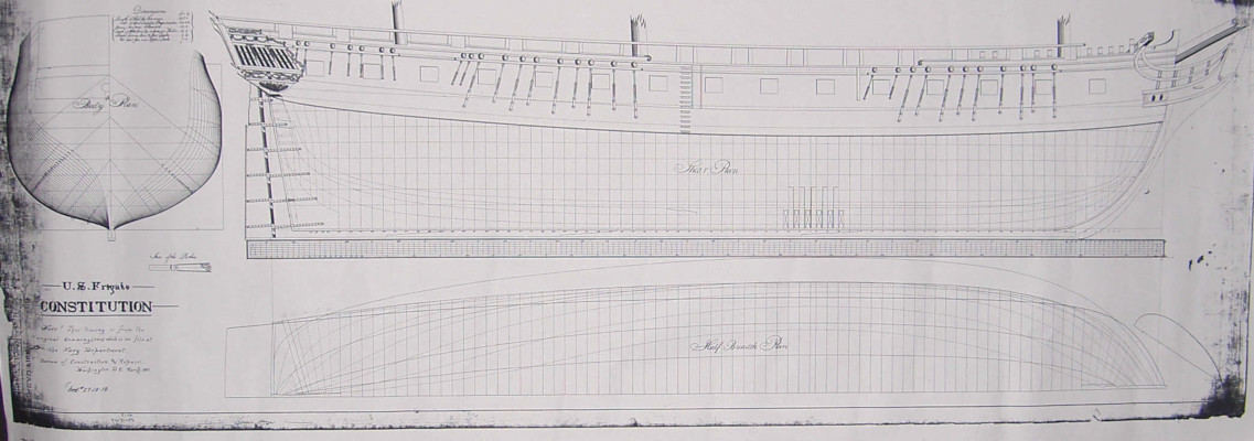
When I decided to build a model of the Constitution, the first question I had to answer
was "Which Constitution?" I had a copy of the "Doughty Draft" from the National Archives,
and was particulary interested in that version of the ship, as it showed her with fancy
head timbers, open railing on the forecastle and quarter decks, and ornate stern quarter
galleries, all features not present on today's ship. This plan, however, lacked any information
about what the transom looked like. I did a great deal of research and reading
on the Constitution and about the various rebuildings and restorations she has undergone.
And about the modifications to her done in the interval between her launch and the beginning
of the War of 1812, when she achieved her greatest fame and looked quite different than at
launch.
A valuable source, among many, is the volume of the "Anatomy of the Ship" series
on the Constitution, written by Karl Heinz Marquardt. The author presents some detail
on the early changes in the appearance of the vessel and also offers up several
reconstructions of the stern, based on contemporary description. After some deliberation
I decided to model the Constitution as she might have looked at launch and to use
one of the reconstructions in the Marquardt book as a guide to modeling the transom.
Early in her career, in 1804, during actions against the "Barbary Pirates" under command
of Edward Preble, she supported the raid by Stephen Decatur to destroy the Philadelphia,
which had been grounded and captured by the Tripoli pirates and was in Tripoli harbor.
Later that year, she was at Malta to be resupplied and collided with the President. In
the collision, constitution lost her figurehead of Hercules and suffered damage to her
head timbers and bow. She was repaired in Malta, but the repairs shortened her beak and
eliminated her figurehead. Constitution remained in the Mediterranean until 1807, by which
time tensions with Britain were increasing and war seemed likely.
Constitution was recommissioned and overhauled after her return. Some time in the
several repairs and rebuildings, rather drastic changes were made in her appearance
and in her armament. The figurehead was not replaced, until 1833, and she probably carried
an ornamental scroll on the beak instead. Her head area was enclosed, obsuring the head timbers
which lost their ornamental trim, and the trailboard was probably simplified. A gun port
forward of the original 15 ports was added, and the open railing of the upper decks was converted
to solid bulwarks with gun ports. When originally built, Constitution did not have
gun port lids for her gun deck ports, except for a temporary lid which could be placed
in the forward port to reduce the water entering that port. With the open waist, the open
railing along the upper decks, and no gun ports, she must have been an extraordinarily
wet ride. The modifications made during these changes addressed those shortcomings, and
also expanded her armament. As the War of 1812 approached, Constitution's battery of guns
probably consisted of thirty 24-pounder long guns plus twenty-two 32 pounder carronades on the
spar deck, located approximately where the original gun placements had been in the open
railing, now behind bulwarks. Two chase guns were positioned at the stern and two at the bow
on the spar deck. In 1810, Issac Hull
was named her Captain. She sailed on diplomatic mission to France in 1811 and returned in
1812, by which time tensions with Britain were increasing, and War with Britain was declared
in June of that year.
Constitution gained her first and greatest fame in the War of 1812. Her exploits created
the legend still known today, from hair-raising excapes from overwhelming British pursuers,
to defeat of multiple British frigates in single ship encounters.
In July of 1812, she first escaped a five-ship British squadron in a two day chase by using
kedge anchors to
gradually pull away and sail to Halifax. After her return to 'Boston, she sailed out in
August in pursuit of a British frigate rumored to be about 100 miles away. This was the
frigate HMS Guerriere, a French built light frigate captured by the British and taken into
the Royal Navy. Guerriere was about 1,000 tons burthen, 154.5 feet long, 39 feet wide and 19 feet deep
and she mounted thirty 18-pounder long guns, sixteen 32-pounder carronades, two 12 pounder
long guns and a complement of 350. Constitution is 1,500 tons burthen, 207 feet long, 43 feet
wide and 23 feet deep with armament of thirty 24 pounder long guns, twoenty two 32 pounder
carronades, and four 12 pounder long guns, and a complement of 450. Constitution certainly
had the advantage of size and firepower, but she also sailed well and was handled well. The
battle was hard fought, and the Guerriere so damaged she had to be destroyed after surrender.
It was during this battle that a crew member of the Constitution saw round shot from the
Guerriere bouncing off the side of Constitution and allegedly shouted "Huzzah! Her sides are
made of iron!" Giving rise to the nickname by which she is known today.
In September, William Bainbridge, senior to Hull, took command of Constituton and shortly
after, sailed with the brig Hornet (18 32-pounder carronades) to interdict British shipping
off the coast of Brazil. There, with the Hornet stationed outside the harbor of Sao Salvador
to perhaps capture a British ship laden with money, Constitution encountered the HMS
Java. Java was a Pallas class 5th rate frigate of 1000 tons, being 152 feet long,
39 feet wide,and 12 feet 9 inches deep. She was armed with twenty-eight 18-pounder long
guns, eighteen 32-pounder carronades and two 12 pounder long guns.
Constitution approached the Java within hailing distance and Bainbridge hailed her.
Java responded with a broadside that damaged the Constitution's rigging, causing her to
draw off to make repairs. When the ships re-engages, Constitution hammered the Java with
broadsides and the Java's response carried away Constitution's wheel, so that the crew
rigged a tiller and steered her with that during the rest of the engagement. Java's
bowsprit tangled in the Constitutions rigging in a way that permitted the Constitution
to continue to fire broadsides into Java, and the Java's foremast fell, and the two ships
separated. Constitution drew off to make repairs and upon re-engaging found Java to be
a defenseless wreck, which surrendered. Java was too damaged to sail, so she was burned, but
not before her wheel was removed and installed on Constitution. Constitution sailed for
Boston for needed repairs. Hornet remained behind in a futile wait for her British prey, which
never left the harbor.
It was after this engagement, which marked the third time a British frigate had been
defeated by one of the new American ships, that the British Admiralty ordered that
their frigates should not engage with the American heavy frigates.
In 1815, the 50 gun ship HMS Leander was dispatched to North America to deal with
the American frigates. Leander was the British equivalent of a heavy frigate, which
put to sea in February of 1814 She was a "fourth rate frigate" of 1500 tons burthen,
being 174 feet long, with beam of 45 feet and depth of 14 feet. She mounted thirty
24-pounder long guns plus twenty-six 42-pounder carronades and four 24-pounder chase
guns.
Meanwhile, Constitution under Captain Charles Stewart made her escape from Boston
harbor and headed out into the Atlantic to harass British shipping. The Leander
set out in pursuit in the company of HMS Newcastle, another British 4th Rate heavy
firgate and HMS Acasta, a fifth rate frigate. Constitution encountered two
smaller British sixth rate ships, the Levant and Cyane, engaged, defeated, and
captured them both. The prizes set sail homeward, but the Levant was overtaken
and re-captured by the Leander squadron. Constitution made her escape from the
superior force, heading west to Brazil, where she learned of the signing of the
Treaty of Ghent, ending the war, and headed home to Boston.
Thereafter, Constitution was variously fitted out for various training
purposes and experimental modifications until, in the very early 20th century,
she was to be used as a target ship and sunk. Congress had authorized her use
as a museum ship, but appropriated no money for this purpose. Once local media
learned of the situation, there was a national outcry and fundraising effort. Congress
finally appropriated a small amount of money for a partial restoration in 1906/
Constitution was extensively restored and rebuilt in 1925-27, after a survey
found her in dangerously poor condition, and a national fund-raising by school
children raised funds for a re-building. After this, she toured east and west
coast ports in 1932-34, passing through the Panama Canal.
Constitution has had several more restorations, and the more recent ones
restored the diagonal hull bracing removed in the mid-1800s when she
was modified with paddle wheels. The removal of the diagonals had resulted
in hogging, with about two feet difference between center of keel and the
ends. Successive restoration have involved replacing rotted wood and
securing supplies of replacement timbers. The last restoration was in
2015-2017 and cost over twelve million dollars.
As a final bit of trivia, the Constitution was the inspiration/model for the
French heavy frigate Archeron, which was an important part of the story of the
movie "Master and Commander: The Far Side of the World" the enemy and nemesis
of HMS Surprise. The special effects crew for the movie surveyed Constitution
in preparation for the movie. Patrick O'Brian based some of the plot of the novel
"Far Side of the World" on the exploits of the USS Essex in harassing the
British whaling fleet in the Pacific during the War of 1812. Since the Aubrey-
Maturin series of books were just becoming popular in America, it was
better to make the enemy French than have the British HMS Surprise battling
an American ship.
Once I had decided to build the hull as it appeared in the 1794 Doughty plan
and decided to build it in 1:64 (3/16" = 1 ft) scale, I set about converting
the ships plans and lined into templates for the keel elements and the frames.
I made photocopies of the plan in the appropriate scale then used these to lay
out the various components. I made the keel, stem and sternpost of red oak. The
frames were made from maple. I first milled some rock maple to desired thickness
and width, then cut the futtock parts out, basing the location and angle of these
cuts on the plans for the frames.
As you look at the plan, you can see that the location of the frames on the keel
is clearly shown, as well as the location/size of the first futtock of each frame.
On the top left is the diagram of the shape of each frame. When building the frames,
it is possible to mill out the wood for them and then lay out the wood on the outline
of each frame and mark the location of each futtock joint, from first to fourth.
To make this easy I just photocopied the part of the plan that showed the frames
outlined, duplicated it in reverse to allow me a diagram of each full frame, then
cut out each frame to use as a paper template when making up the frame halves to
rough outline. Note that on the ship plan, the frames are diagrammed and numbered
starting in the middle of the hull and going forward and back, so you have to
copy the plan in reverse and piece the halves together or trace the outlines
to get the full frame templates. I lay out and glue up the futtocks for both halves
of each frame at the same time, working over the paper template covered with waxed
paper. Once the glue is dry, I glue the paper template to the rough frame and saw
out the frame on the outside margin of the frame.
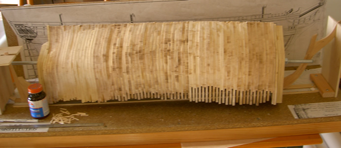
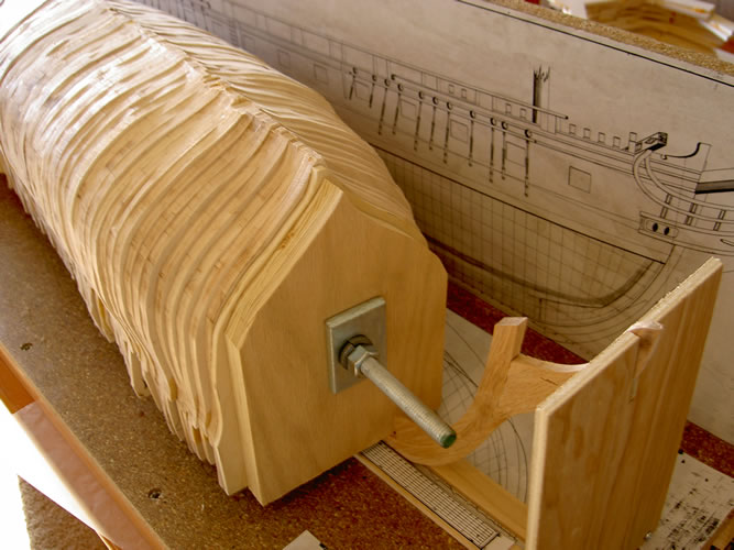
In the case of the Constitution, I then bolted all the full frames together and used
a power sander to sand the outside edges of the frame and also taper them fore and
aft for the later planking. The half frames, cant frames, and hawse timbers were added
and shaped later after the full frames were set up on the keel.
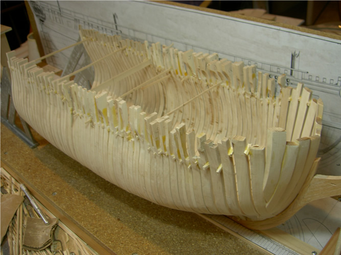
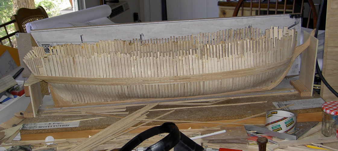
These pictures show the full frames bolted together ready for sanding and finishing the
outside. After that is done, and the tapering of the forward and after frames approximate,
I unbolted the frames and cut out along the inside of the template for each frame. The bolted
frames in this picture are resting on the buiding board, which secures the keel and has
notched plywood pieces at each end to secure the beak/stem and the stern post and keep them
plumb. you can see the paper template (taken directly from the plan, marking
the stations alongside the keel, and on the back of the board, there is a copy of the full
size plan, both helping in positioning and aligning the frames.
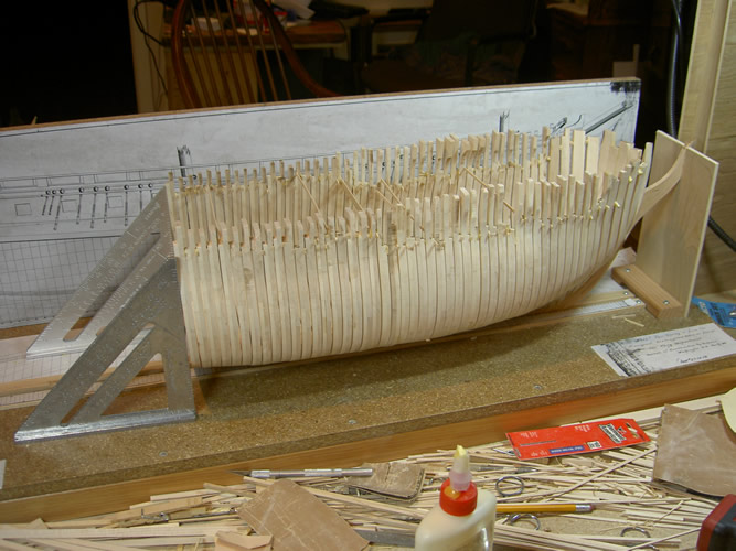
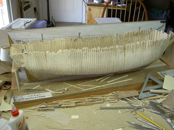
Below are pictures of the hull after starting to set up the forward frames. The keel is held between
wood strips on the building board and the stern and stem held plumb. The carpenter squares you can
see toward the stern are used to keep frames plumb as the glue sets. Because the "make
and space" of the actual ship is 22" and 2", I have used 1/32" spacers (scale equivalent of 2")
between the frames, which also helps keep them aligned as you work forward and then aft.
All these "tricks"
helped make the framing easier, but not nearly as easy as the Hahn method, discussed in the notes on building
the Raleigh.
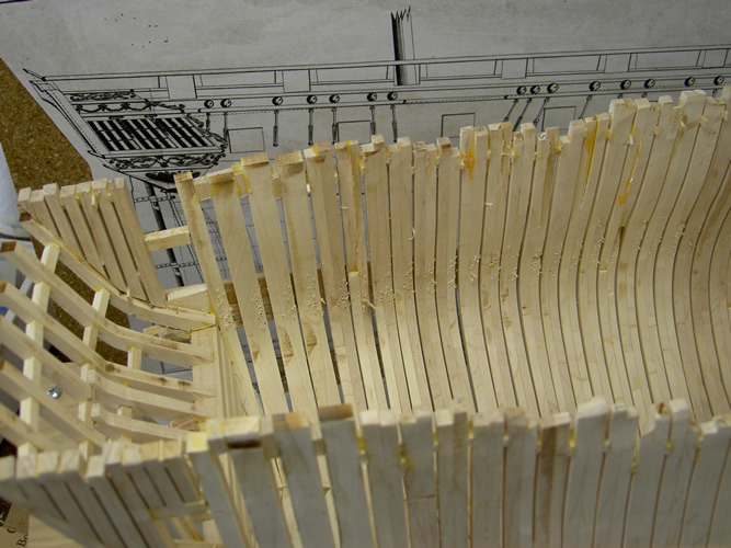
I first set up the forward frames including the cant frames and the hawse timbers. Once
the glue was dry and the structure stable, I repeated the process to set up the after
frames.
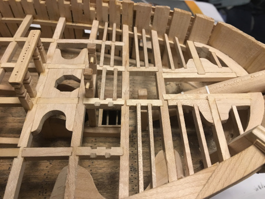
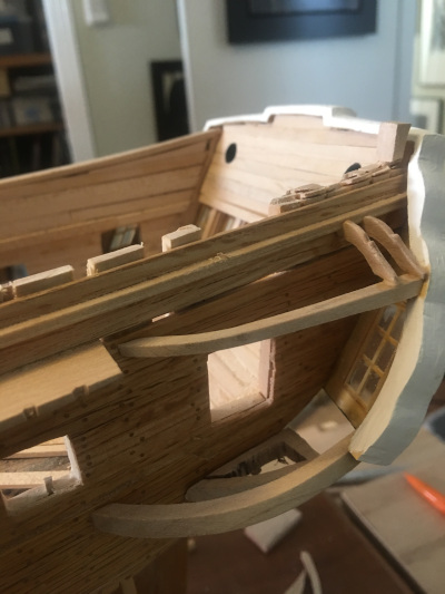
Setting up the frames completed, including the after frames, and
the wing transoms. The left hand picture shows the hull and the right hand shows the
framing of the stern and transom.
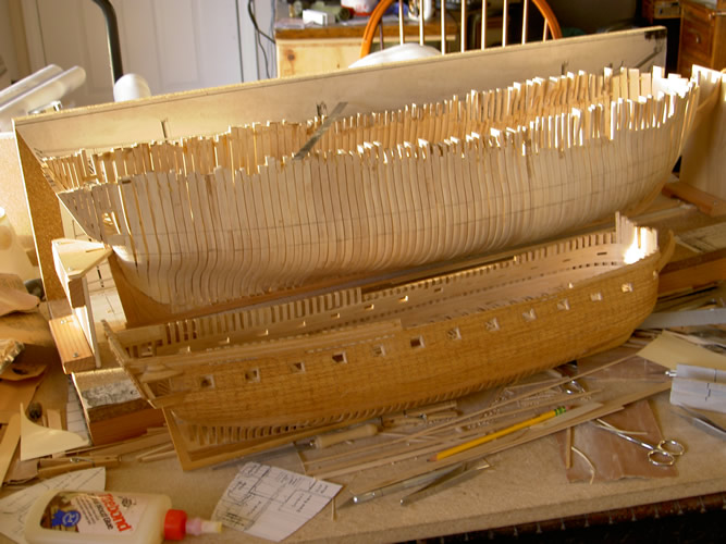
These final shots of the framing of the hull show, on the left, the Constitution
with all frames set up and still on the building board, with the hull of the
Raleigh in the same scale in front of her. These two vessels were both "frigates" but were
markedly different in hull design and construction. And therefore in the armament they
could carry.
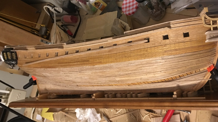
The picture on the right shows the Constitution with wales installed as I started to
plank the hull. Once the wales are in place, the hull is very strong and can be
removed from the board as the planking continues. I planked one side of the hull
completely and the other from the wales up. I used the building board as storage for the
hull and built a sturdy plywood box to hold the board and model. It spent most of the
next 15 years in the box.
One of the reasons for the delay in working on the Constitution was that I was
grappling with the realization that, if I built her as a fully rigged model, it
would be a huge model and require a huge case. With the Vandalia already on display,
and the Raleigh next in the queue, I was beginning to comprehend that there just
wasn't enough room in our house, or any likely future house of ours, to hold all the
models I planned to build.
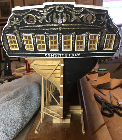
So I compromised a bit. I went ahead and finished planking the port side of the hull,
and worked up a transom out of boxwood, using the conjectural reconstruction in the
Marquardt "Anatomy of the Ship" on the Constitution. It is a reconstruction
of the transom as it probably looked in 1803, before the collision with the President
in Malta, which damaged the bow extensively, and also damaged the stern. It was
the repairs done after that accident that began the series of changes to the ship
producing the version best known for her exploits in the War of 1812.
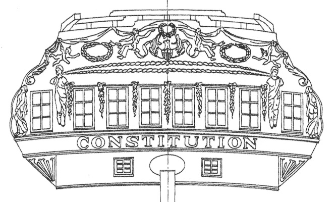
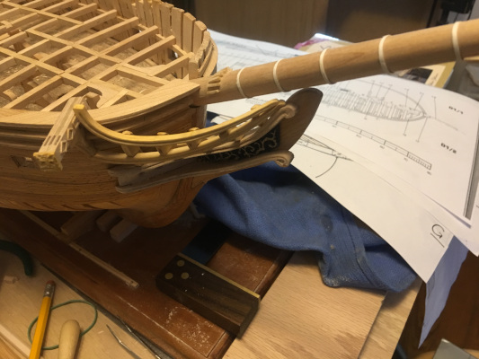
Here is a photo of the plan I used to carve up a transom of thin sheets of
boxwood. The sheets were about 1/16" thick, and I butted two together then
used rubber cement to glue a full size copy of this diagram to the sheets.
I then used my rotary tool with various engraving bits as well as hand
engravers to do the carving. In the process, I cut out the window openings
and the small gun ports just below the railing. I carved the window openings
including the window frames to make later framing of the windows easier. Then
I put the transom in a bag and stored it away with the half-planked hull. For
about five years.
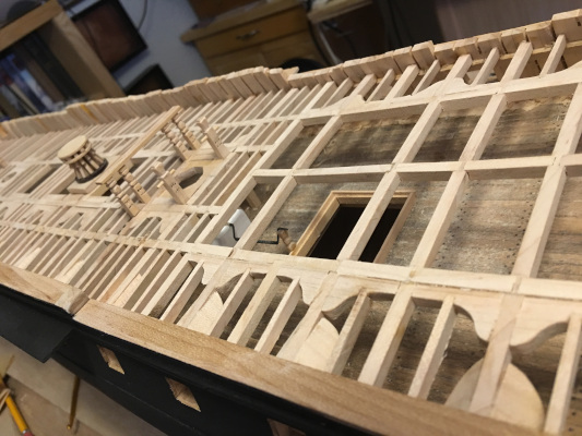
When I finally got the hull out of its storage box and had decided how I wanted to
complete the model, the rest of the construction went fairly fast. Since the
spacing of the frames, with a mere 1/32" between them made the interior pretty
much invisible, I did not need to build the orlop deck or
the berth deck. Also, since I planned to fully plank the gun deck,
I just installed the main beams for the deck, with a
few extra to frame up hatches and such, then planked that deck. I framed for
the transom and the cabin interior so that I could run the planking up to it and
get ready to finish the inside of the transom and cabin.
That said, When it came time to frame up the spar deck - the quarter deck, forecastle,
and gangways in the waist connecting them - I discovered that there are multiple
diagrams of the framing of Constitution's decks. This probably reflects changes made
in the various
re-buildings of the ship, but it does call for some judgement as to which
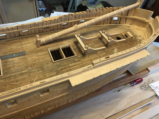
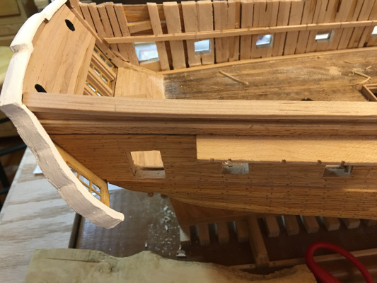
source or sources to use. Below are some pictures of the gun deck after planking.
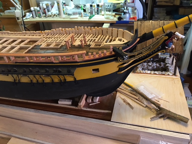
As I finished the bow area, beneath the forecastle deck, I also added details
such as bitts, hatch coamings, and so forth, and modeled the bowsprit. After I
had completed the bow deck planking, I added the railing and channels to the hull
and moved back to complete more details, such as pumps, and interior cabin detail.
On the left is a picture of the forward part of the gun deck with bow sprit
fabricated and put aside. The clamp for the spar deck (forecastle) is in place.
The picture on the right shows the after part of the gun deck, in the cabin, and
you can see the main railing, trim, and channels are installed.
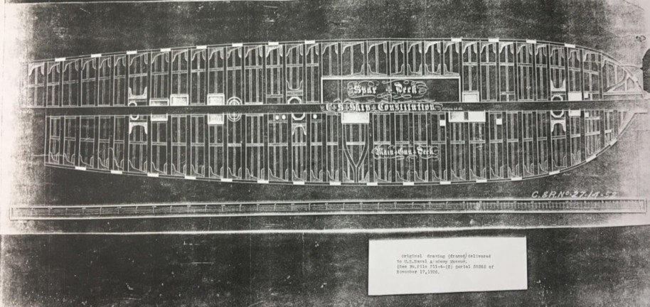
As mentioned, I had a plan for the framing of the gun deck and spar deck that
looked like it might be contemporary with the 1925-27 rebuilding, so I used that
plan as a starting point for reconstructing the timber framing of the spar deck,
adjusting the plan as I saw fit, using the Marquardt text as an additional source.
Here is a picture of that 1927 framing plan.
Before I started on the framing of the spar deck, however, I installed the ceiling on the
inside of the frames on the starboard (finished) side, then did the final cutting out of
the gun ports. Then I installed the clamp, the carrier for the deck beams. Since the clamp
had to curve around the bow, I
made it up of two thin strips of wood to accommodate the required bends.
Here are a couple of photos of the installation of the main rails, the trim and the
clamps, and of the ceiling.
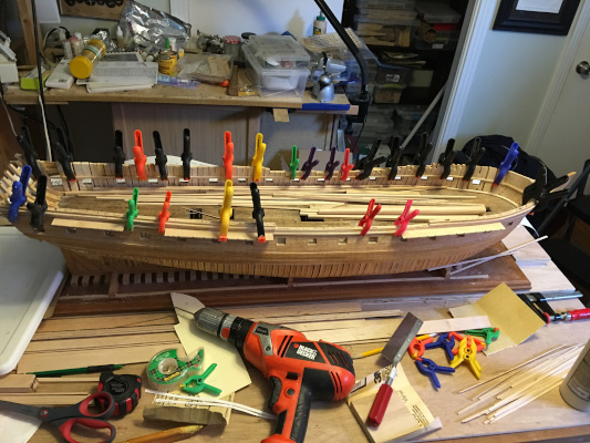
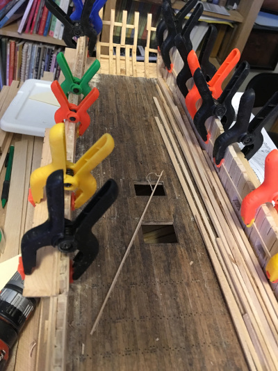
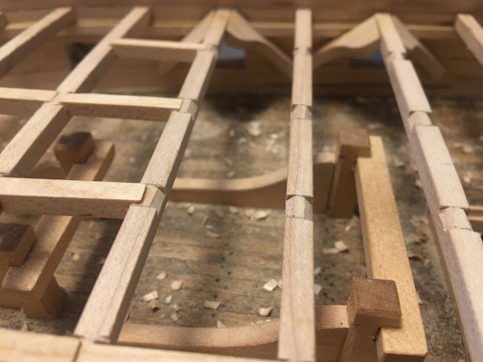
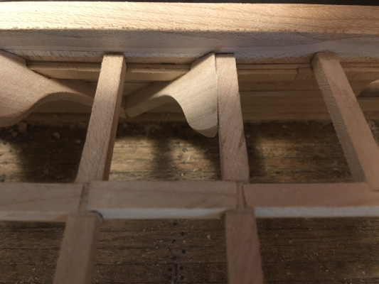
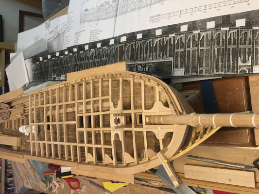
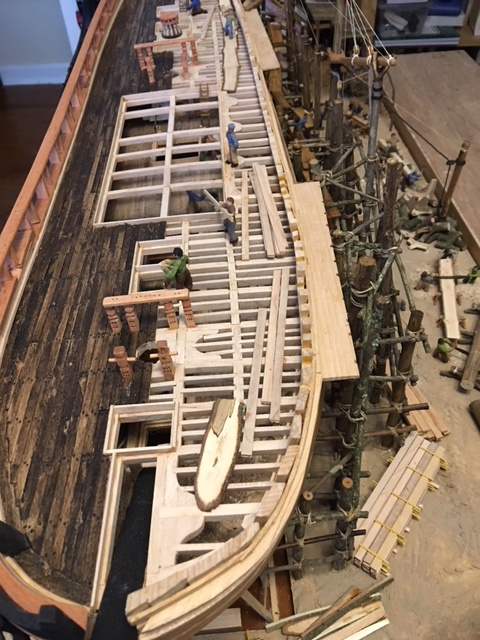
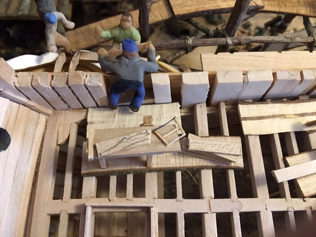
Below are some pictures of the framing of the spar deck, starting with the forecastle and
moving back to the stern. The main beams are first fastened to the clamp. Once secure, the
framing is laid out and location of notches in the beams marked with pencil. These notches
will accomodate the tapered ends of the crossing timbers, the "carlings", which ran
fore and aft to brace the main beams and to support the "ledges" yet smaller timbers that
ran athwartships between carlings and in turn supported the deck planking.
As is inevitable in ship modeling, sometimes you have to leap ahead and model something
that would seem out of order in the way an actual ship would be built. It is necessary,
for example, to build bitts and other "deck furniture" on a deck which will be covered
by a second deck before building the second deck and thereby restricting access to the
work area. Similarly, I added the "hanging knees" to the main deck beams before installing
the carlings and ledges, since the latter would make access to the main beams and the
frames/ceiling impossible. As with the issue of what the deck timbering looked like, there
was confusion around what the hanging knees might have looked like and how and where
they were installed. I looked over several plans showing how the hanging knees were
positioned, and found one that was particularly elegant, with the hanging knees installed
at about a forty-five degree angle to the deck, two knees to every other main beam, set up
to straddle each gunport of the gun deck. Hanging knees were often of very odd shapes
because they had to be positioned to not obstruct a gunport. The plan I found, solved
the problem elegantly, so I did the knees that way.
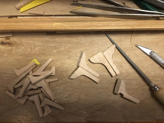
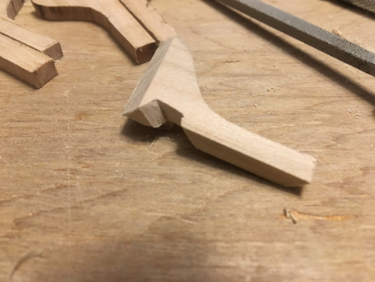
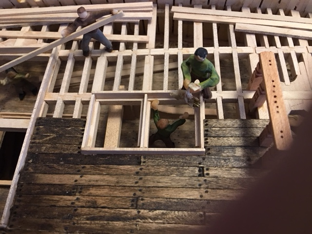
Here are some photos of how I fabricated and installed the hanging knees
and the lodging knees. The hanging knees were cut at an angle to butt against
the main beam and notched to accomodate the clamp. Lodging knees are cut
square and butt against the beams lying in the same plane as the beams, unlike
the hanging knees, which extend downward.
Here is a photo of the framing of the forecastle in progress. The breast
hook is in place, and the main beams. Hanging
knees are installed, but only on the starboard "finished" side, and lodging
knees and various similar bracing elements installed at stress points,
such as around the mast and bowsprit. A bit further along, the catheads
are made up and the head timbers installed.
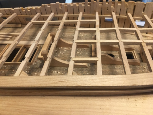
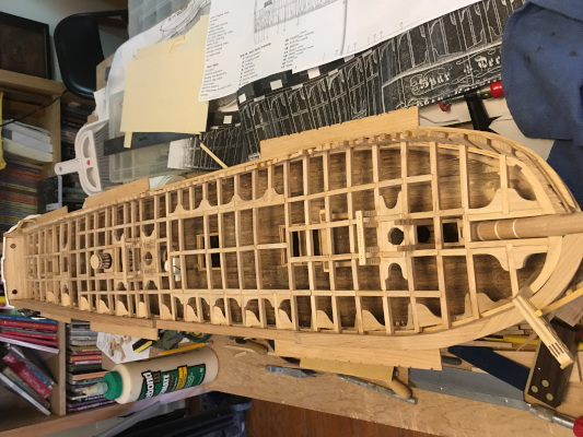
The shots below are of the timber framing proceeding back from the forecastle. On the left,
the deck timbers are in place back to area where the quarterdeck planking begins. On the
right, the main beams, carlings, hanging knees, and lodging knees are in place and certain
deck elements
installed (capstan, bitts) before working on the ledges. See below for notes on the
make up of the beams in the waist.
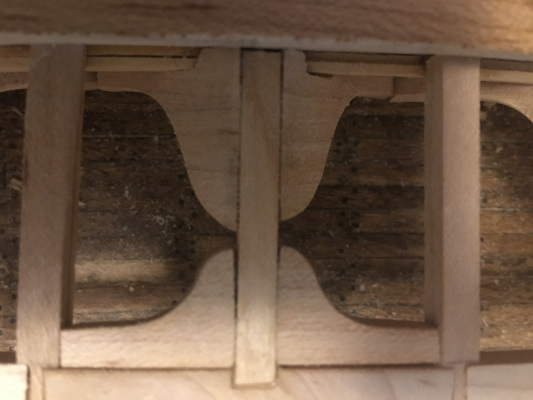
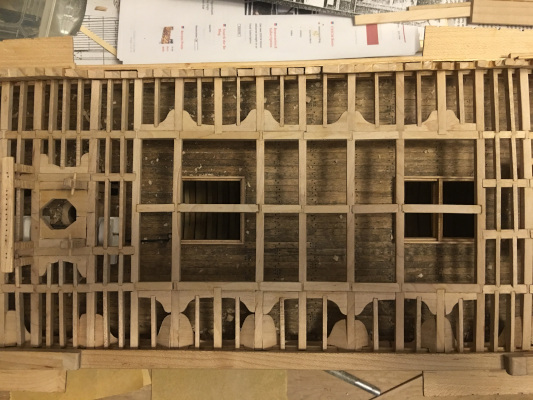
On the left below is a photo of the waist framing with ledges installed. Plans for this
area of the deck varied in both the spacing and the layout of the main timbers and the
large center carlings. Since the center carlings were removable in areas over the hatches,
I went with the plan that showed the deck beam spacing that provided proper hatch
access. The photo on the right is a perspective shot showing how the deck looks before
planking.
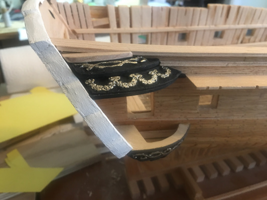
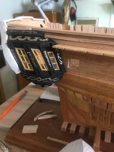
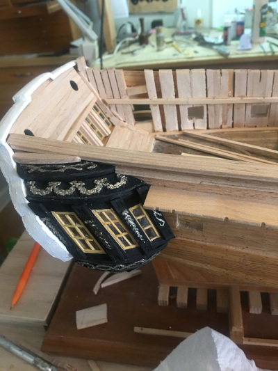
Before installing the spar deck/quarterdeck timbers, I had made up the quarter galleries
and installed them. The starboard gallery is finished and painted. The portside galellery
is modeled as it might have looked being framed up, with intent to show more of that
process in the diorama.
At this point, I had the head timbers finished, with painted trailboard, and the
gallery finished and painted on the starboard side, which was to be the finished
side in the diorama. I had planned to leave that side unplanked below the wales
and painted from wales up, but at that point concluded that it would just look
not right to do it that way. So I finished planking the hull on that side. Not a
reccommended order of doing the work, but things change as a model evolves.
Then, after planking one side of the spar deck, I added the railings for the spar deck,
which are open according to inforamtion
from the Doughty plan and other sources at the time of launch. When building the railings
I cut notches in the main rail and even into the planking as needed to create the gun
ports again using the Doughty plan as guide. Also, I modeled the figurehead,
Hercules resting on hand on the fascicles ("e pluribus unum") and holding aloft the
constitution in the other, installed deadeyes, and did the final staining and painting of
the "finished" side of the hull. . Since the center carlings were removable in areas over the hatches,
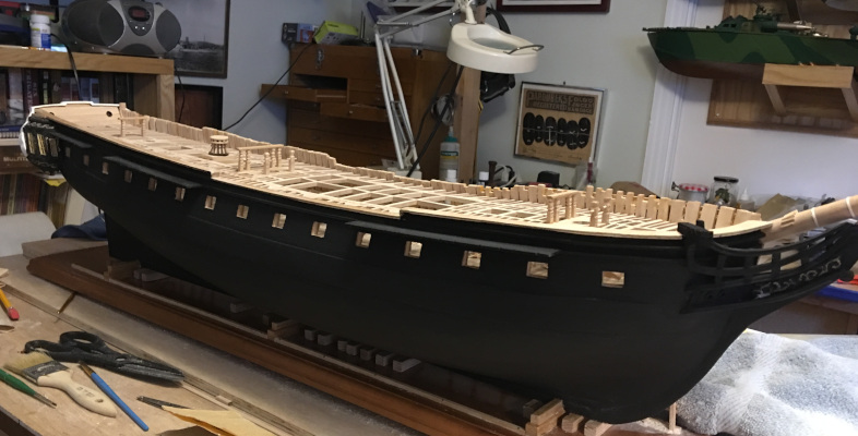
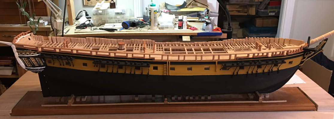
Following ares some pnoto of the model after painting. The first before railings were
installed, the second after.
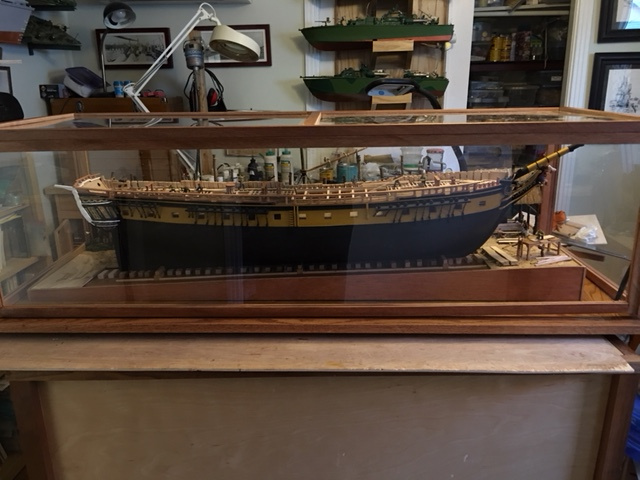
At this point I had a pretty nice hull model of the constitution as she probably
looked at launch in 1797. It was mounted on ways on a hardwood base and could
be displayed and make a fine model. But I was committed to the shipyard diorama
idea, so forged ahead.
Constitution's keel was laid down on 1 November 1794 at Edmund Hartt's shipyard in Boston,
Massachusetts under the supervision of Captain Samuel Nicholson and master shipwright
Colonel George Claghorn. She was framed of southern live oak, and by the time a
peace between the United States and Algiers was announced in March 1796,
Constitution was partly completed. Construction on all the frigate halted
as per the terms of the Naval Act of 1794. However, with the urging of President
Washington, Congress agreed to continue the construction of the three vessels closest
to completion, The United States (44), The Constitution (44) and the Constellation (38).
Work on the remaining frigates was halted and materials diverted to finish the three
under constuction, stored, or sold off.
The shipyard attempted to launch Constitution on 20 September 1797
with President John Adams and Massachusetts Governor Increas Sumner in attendance.
However, the ship only slid down the ways about 30 feet before
becoming stuck, likely because her extreme weight had caused settling of the ways.
Two days later, she moved another 30 feet, but did not finally launch
until 21 October, after rebuilding of the ways.
Some said that the difficulty in launching the ship bode ill for her future. They
were wrong.
To model the shipyard, I first needed to decide on how to make the base for it.
I wanted the ground beneath the ship to slope gently toward the water, as would be
the case for a shipyard of the time. So after deciding how large to make the base,
I made up tapered sides which mounted on the plywood base and supported a second
piece of plywood that enclosed and surrounded the model base. I made the base so
that the model could be removed, if in the future one wanted to display it separately.
For this model, I used Super Sculpy to model the figures. In most prior models, I
had carved figures from boxwood, which is a fine way to do it, but time-consuming.
During a break from modeling sailing ships, I build multiple models of PT Boats,
which were radio-controlled, culminating in a 1:16 scale model of an early Higgins
PT Boat with working torpedoes launched from torpedo tubes and manned by an eleven man
crew (on deck) sculped from Sculpy, a heat fired polymer clay. That project worked out
well,
so I decided to use the same material for the fifty plus figures I planned for this
diorama, largely because making them from Sculpy was much, much faster than carving
them from boxwood.
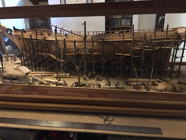
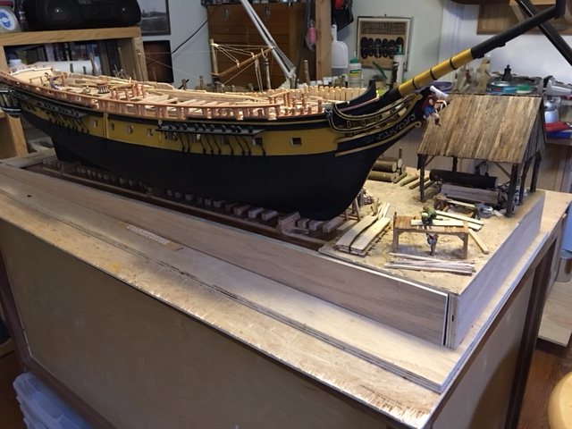
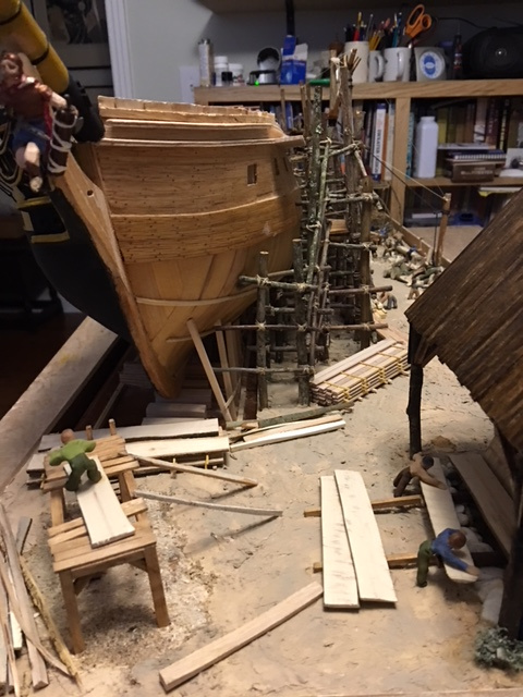
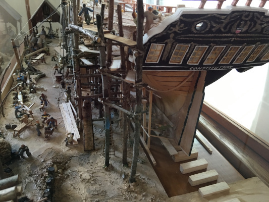
Here are a couple of photos of the finished diorama. The first shows the hull on the
ways, ready to launch. The second shows the unfinished side, with the dockyard at
work on her. Pictures below these show the construction of the dockyard detail.
Following are some notes on construction and plenty of pictures of the work in progress
and the final result.
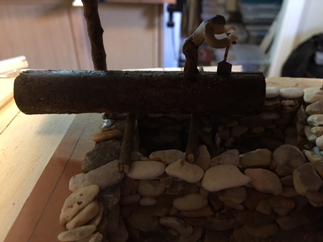
The first two photos show the bow of the hull on the dorama base. In the first picture,
the first pit saw has been built up of matboard, small stones, latex wood filler, etc and
then set into a hole cut in the base for it.
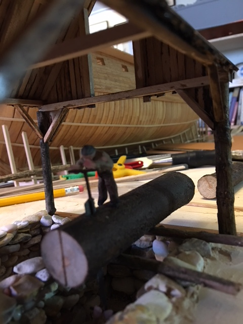
In the second picture, the shed over the first pit saw is up and the second pit saw, on an
elevated stand is modeled in place, cut lumber is stowed nearby, and you can see scaffolding
behind the hull.
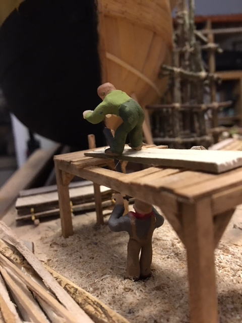
Below those two are additional detail photos of the pit saws and the figures working them.
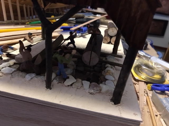
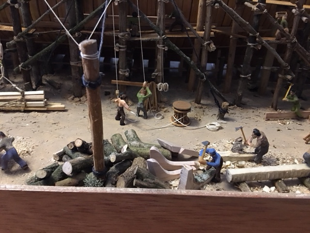
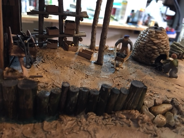
Once I had the pit saws placed, I went down to the other end of the diorama to build
a blacksmith shop. I first built a small raised area, on about the same level as the
opposite end where the pit saw was. I imagined that the smithy might be placed near
the water for safety's sake, so I planned to build up a little shoring along the waterline
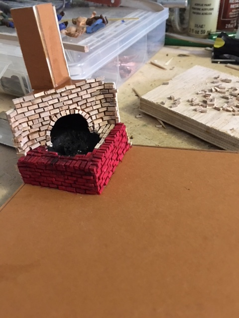
where the ground sloped down to the water. First I built the forge onto a piece of matboard
the size of the place I planned to put the workshop. The forge was roughed up in
matboard, then covered with small wooden "bricks" and the forge and fire made up of
bits of wood and lots of glue.
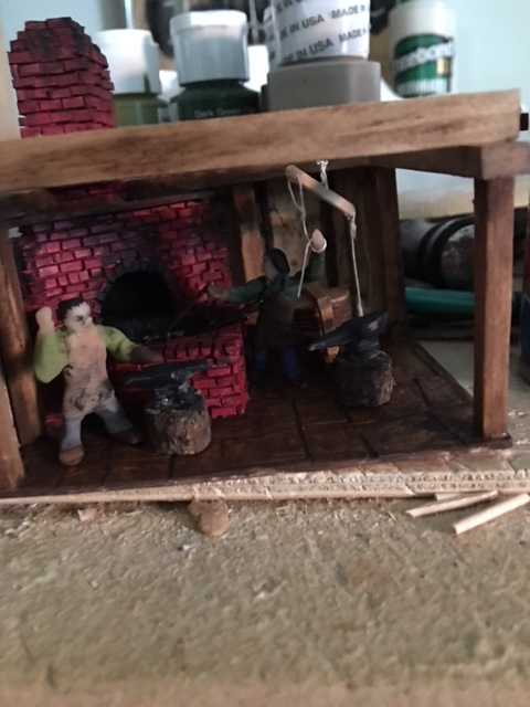
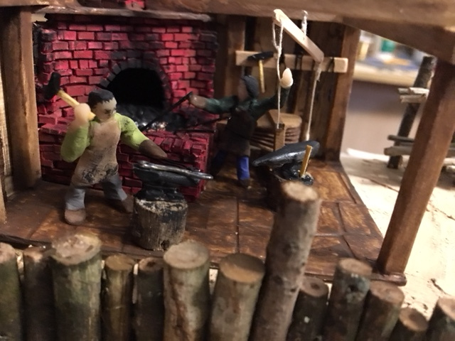
With the forge and chimney in place, I then framed the building in scale timbers,
made two walls of wide planks, installed a bellows, added anvils and tools and modeled
the shop as if it were forging the ironwork for the deadeyes. I planned to have the
deadeyes being turned up by pole lathe operators nearby.
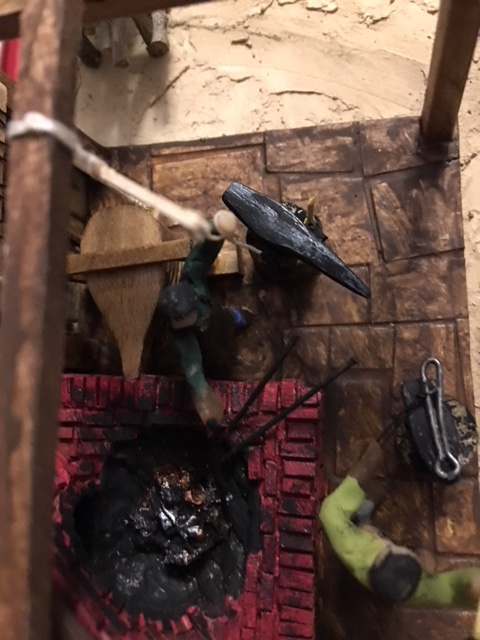
The picture above shows the smithy just before adding the roof. There are two smiths
working on two anvils, and one is pumping the overhead bellows.
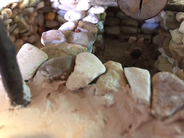
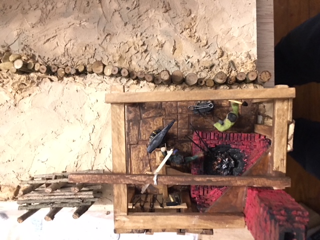
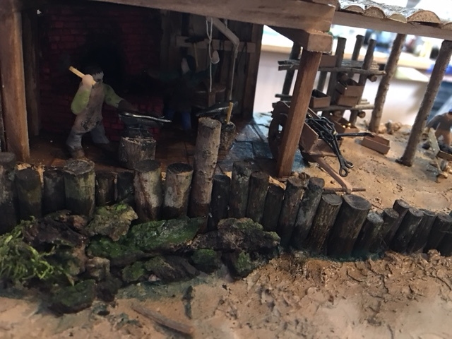
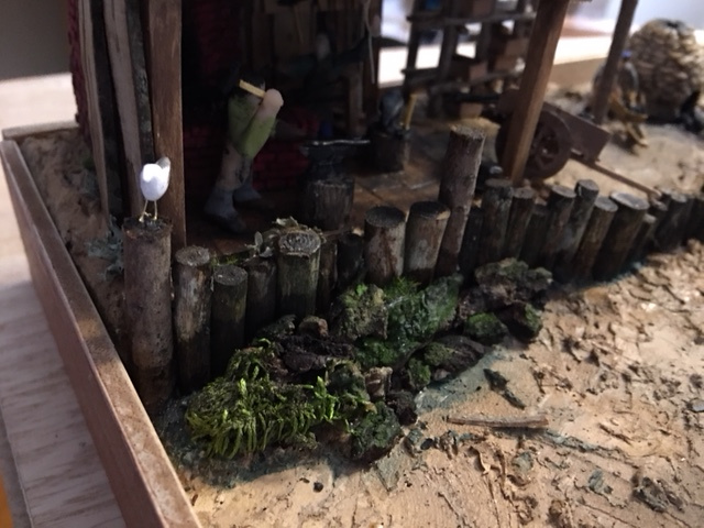
The picture below shows the smithy when finished, with the roof on, the shoreline reinforced
with timber piers and rocks. The rocks were finished off with more latex wood filler to model
the sandy shallows and with moss and paint along the rocks. You can see the storage racks for
iron stock and the tote boxes holding work in progress. Later I added the kiln for making
the charcoal for the forge.
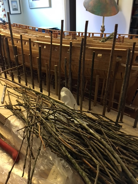
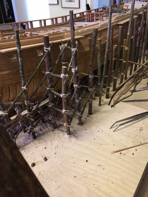
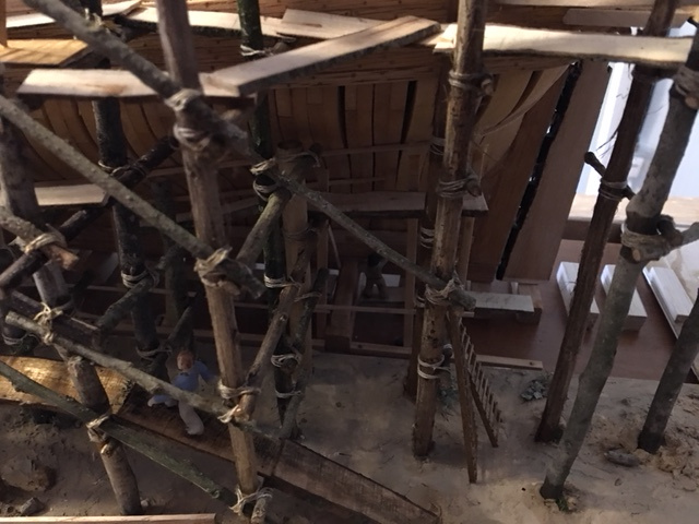
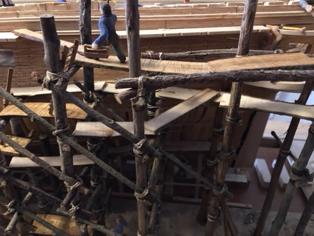
With the two small structures at each end of the diorama, I completed the scaffolding along
most of the hull. I had gathered a few shoe boxes full of small branches and twigs in the
neighborhood over the several preceeding months, so I had a great selection of small straight
stock to use for this purpose. I first chose the uprights and glued them to the plywood base.
Then I put a few of the horizontal and diagonal bracing members in place. Once the uprights
were secured, I modeled the soil surface and some rocks and some dirt from excavating for the
poles using latex wood filler. Later I stained this with a thin wash of acrylic paint in
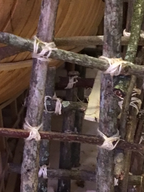
various ground colors. When erecting the scaffolding I also incorporated the masts for the
derrick and its rigging. The scaffolding was lashed together with cotton cord. When I had
worked for a time in Riyadh, the multi-story building under construction all were built using
bamboo scaffolding lashed together, probably with jute fibre. So I figured that an 18th
century shipyard probably had similar scaffolding, without the bamboo.
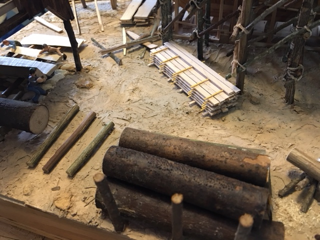
I cut some small branches, from 1/2 to 1 inch diameter into planks on my bandsaw. I used these
for cut lumber being stored on the site, for siding and roofing on the buildings, and for
planking on the scaffolding. Some of the branches I had picked up had "spalted" from the
ground contact and made very splendid looking planks. I cut them into various thickness and width
for the stock of lumber on hand. Also, these pieces were used in modeling the pit sawing and the
crosscut sawing operations.
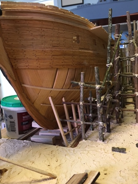
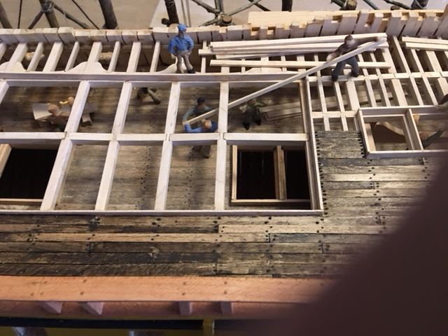
I built the scaffolding leaving enough space to model the additional processes I wanted to
show. The storage of cut trees to be sawed for lumber, the collection of curved timber and
tree crotches for specialty framing, the squaring of timbers, the shaping of curved timbers,
the lathe turning of spindles (or in this case deadeyes), the making of charcoal, as well
as the carpenters planking and framing the ship and hoisting the lumber up to the upper decks
for those purposes. Once the scaffolding was in place, I planned out the rest of the diorama
to fill in the space available.
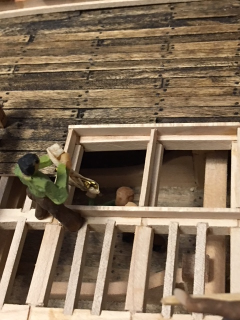
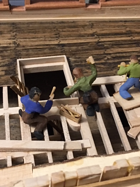
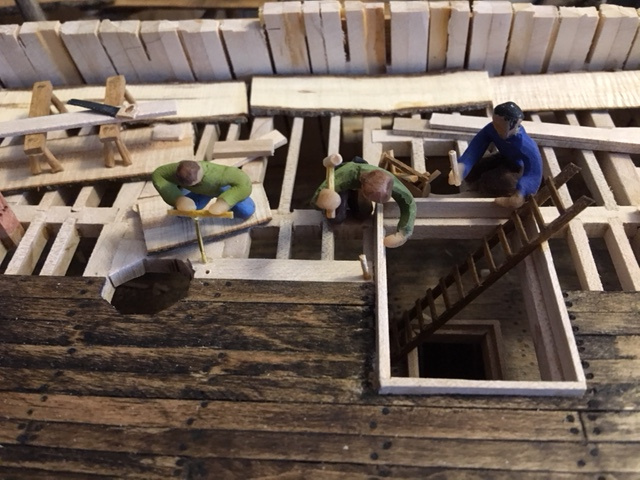
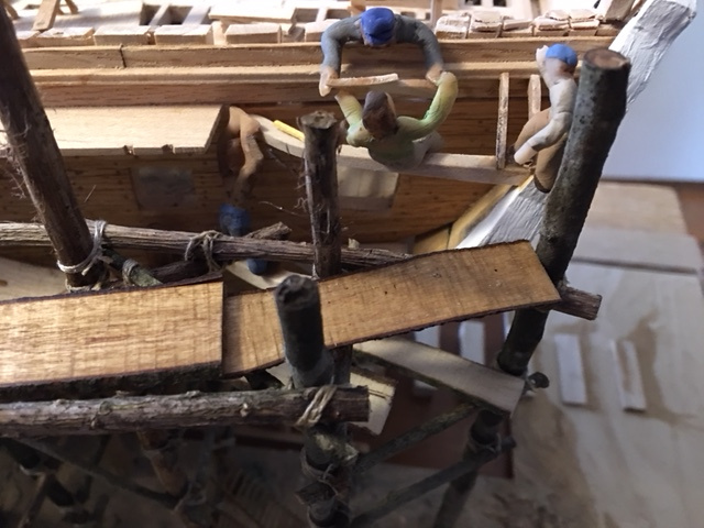
Below are some pictues of the scaffolding at various stages of completion, and in final
state, with carpenters at work beneath it, and on it.
Most of the rest of the work on the diorama consisted of filling in available space
with the activities I wanted to show and finishing up the details of the ground -
the bare dirt, scrubby weeds and shrubs, rocks, gravel, and so forth. For the most part,
I worked from the area of the pit saw back toward the smithy. I first set up a
stockpile of large tree trunks as supply for the pit saws, and I also placed some
sawed planks in stacks around the base of the scaffolding, and some in the upper level
of the house for the larger pit saw. Then I set up an area for cross cutting planks and
round stock.
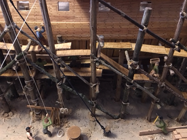
I then set up the derrick preparing to hoist a load of sawn stock up onto the deck. I
imagined that a shipyard would have a capstan to do the heavy lifting as well as ropes
to maneuver the horizontal part of the crane much as on a ship, since the larger yards
of a ship were used as cranes all the time when loading or unloading stores or moving
the ships boats or reloacting heavy stuff anywhere on deck or between hatches. So I modeled
the derrick this way, with a set of capstan bars at the ready for when the hoisting would
be done.
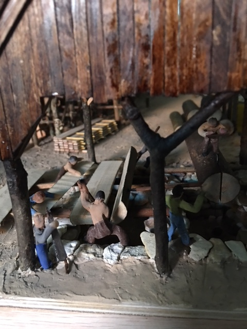
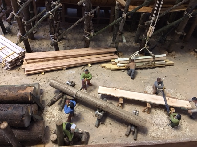
Then I built up a stockpile of curved timbers and the men working them into various shapes,
particularly for "knees". This involved the "bodgers" or adze-men shaping the curves
as well as rough squaring the pieces. And also involved the crew squaring round stock into
material for beams - the fellow with the broad axe is squaring a large beam, and his
work would be followed by a man with a large chisel - the "slick" - smoothing the surface.
I did not model the slick, as I ran out of space.
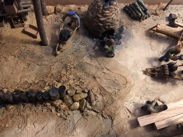
In the space left, I set up two pole lathes and modeled the operators turning deadeyes
out of lignam vitae. In the real world of that time, I suspect the pole lathes would have
been at least under a roof, if not enclosed, due to the generally bad weather in New England.
But for my purposes, I left them outdoors. Near the lathes you can see a fellow boring the
holes in the deadeyes and a second man with a
wheelbarrow taking the finished deadeyes over to the smithy for the addition of the iron
stropping and the chain. He will pass by the charcoal kiln, where one man is
unloading the kiln and a second is taking the charcoal over to the smithy for the forge
fire. The stockpile of hardwood for more charcoal is beside the kiln.
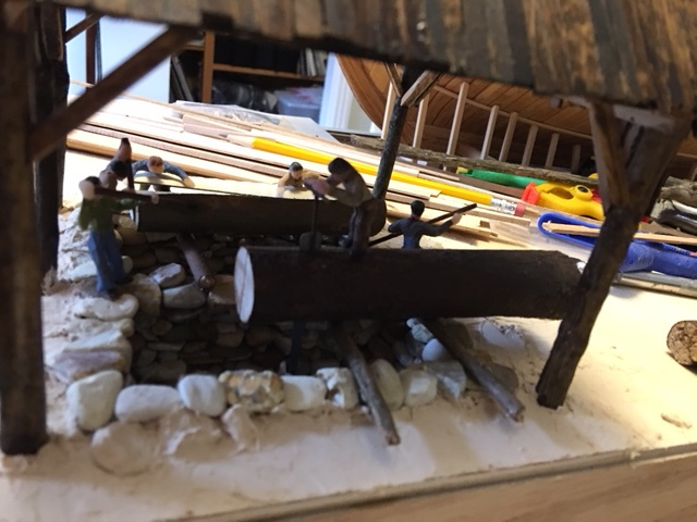
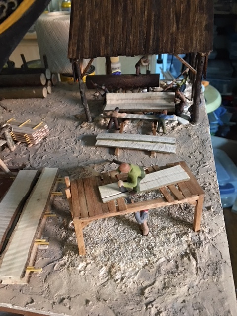
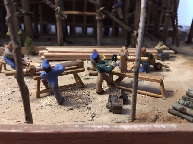
A shot of the timber stockpile for the pit saws and next to it the crosscut
sawyers, with piles of "stickered" cut lumber in the background.
The crosscut sawyers. In the background, another crew readies a load
to be hoisted to the deck.
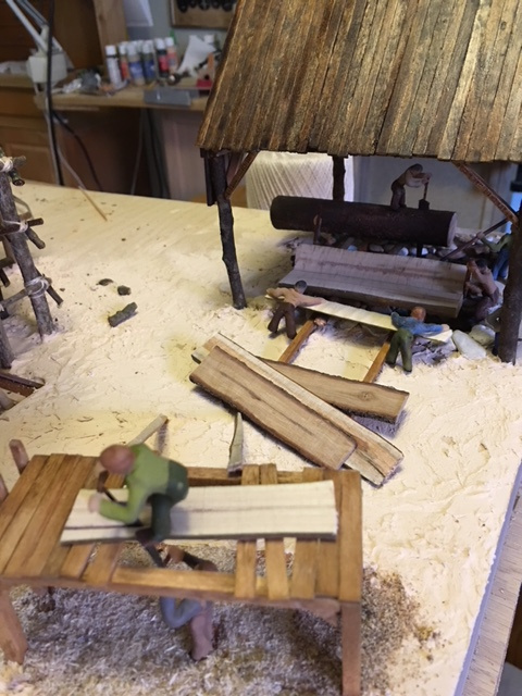
The stockpile of curved timbers is being worked up into knees for the
deck timber framing underway above on the deck. In the background, a crew prepares
a load of lumber for hoisting onto the deck with the derrick/crane.
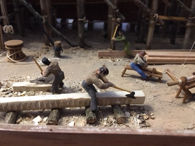
Timber squaring: One man is using a broad axe to square a large timber. Another is
using an adze for the same purpose on a smaller curved timber. In the upper right,
and adze man is squaring the edge of a large plank, and in the mid ground, a man
on a shaving bench is doing the preliminary rounding on a piece to be spindle - turned
later. On the right you can see the drive mechanism for the pole lathe - a rope
passes down from a spring-like sapling tree end, around the drive shaft, to a foot
treadle operated by the turner. The treadle presses down, pulling down the tree, which
then springs back, turning the driveshaft and the process repeats, each passage turning
the shaft in the opposite direction. Pole Lathe.
Another shot of the two pole lathes which the operators are using to turn deadeyes
from lignum vitae blanks. Behind them is the man boring the holes in the deadeyes
with an augur, and behind him, and "idler" lounges on a pile of lumber awaing his
next task assignment
The shots above show the charcoal kiln, which stands next to the storage shed
for iron stock attached to the smithy.
An overview of the kiln and adjacent smithy.
Once I had the ground level activites pretty much the way I wanted them,
I switched over to adding figures and activities to the deck. I wanted to model
men working on installing knees, planking the deck, and framing the quarter
gallery, as well as handling lumber and supplies and walking to work.
Above are a couple of photos of men handling the lumber and supplies for
the deck planking and finishing the ceiling.
The larger photo shows a larger view of the same activities.
Assistants are delivering supplies on the left, and on the right and below, carpenters
are adding planks to the deck.
Carpenters cutting and installing framing of the quarter gallery.
And a few final shots of the finished diorama.